输入捕获
使用通用定时器输入捕获功能测量PWM信号的频率
使用板载的XL550产生PWM信号,电路图如下:
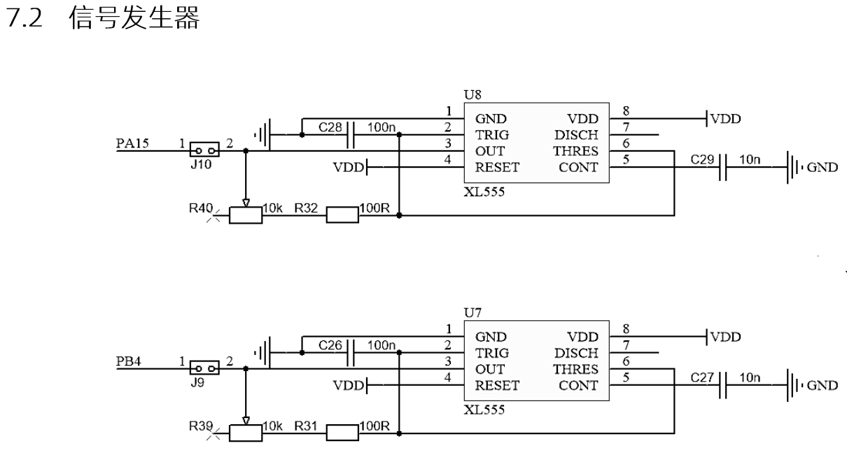
驱动思路
使用定时器主从模式和输入捕获模式,当信号输入发送上边沿跳变时,触发CCR锁存CNT值,触发reset清空CNT,这样我们只需要在特定时间读取CCR的值,通过 计算出频率。1
应用实例
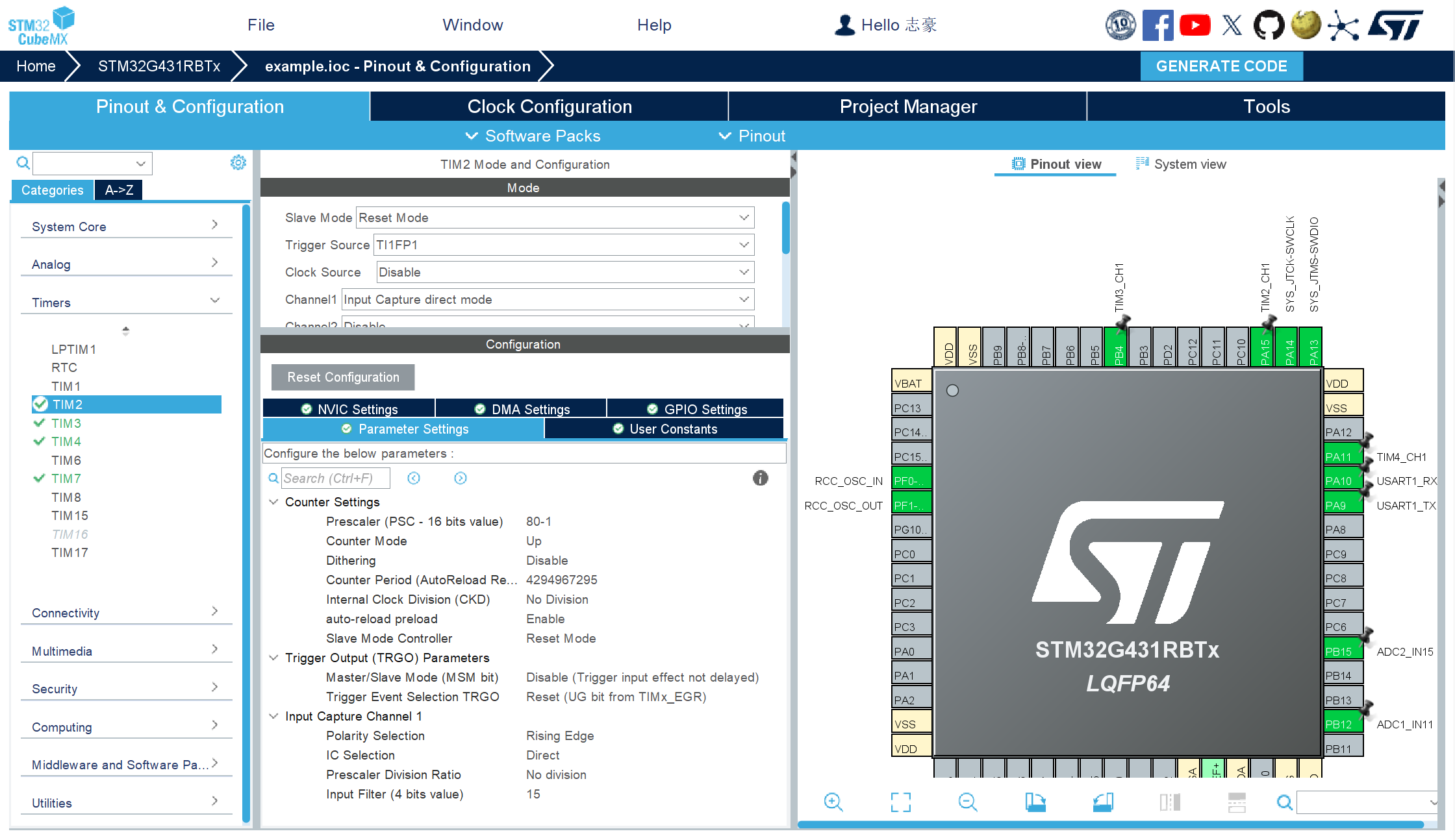
初始化外设(cubx)
提示
以TIM2CH1为例
处理线程
freq.c
#include "app.h"

typedef struct
{
  HAL_TIM_StateTypeDef state;
  uint32_t ccr;
  uint32_t freq;
}freqData_t;

freqData_t tim2Ch1;
freqData_t tim3Ch1;

uint32_t ch1_cnt = 0;
uint32_t ch1_freq = 0;

void FreqTask(void *arg) {
  HAL_TIM_Base_Start(&htim2);
  HAL_TIM_IC_Start(&htim2, TIM_CHANNEL_1);

  HAL_TIM_Base_Start(&htim3);
  HAL_TIM_IC_Start(&htim3, TIM_CHANNEL_1);
  while (1) {
    tim2Ch1.ccr = HAL_TIM_ReadCapturedValue(&htim2, TIM_CHANNEL_1);
    tim2Ch1.freq = 1000000 / tim2Ch1.ccr;
    tim2Ch1.state = HAL_TIM_IC_GetState(&htim2);

    tim3Ch1.ccr = HAL_TIM_ReadCapturedValue(&htim3, TIM_CHANNEL_1);
    tim3Ch1.freq = 1000000 / tim3Ch1.ccr;
    tim3Ch1.state = HAL_TIM_IC_GetState(&htim3);

    /* app start */
    debug("tim2Cn1_state ret:%d",tim2Ch1.state);
    debug("tim2Cn1_freq:%d hz", tim2Ch1.freq);

    debug("tim3Cn1_state ret:%d",tim3Ch1.state);
    debug("tim3Cn1_freq:%d hz", tim3Ch1.freq);
    /* app end */
    osDelay(500);
  }
}
测试结果
[debug] tim2Cn1_state ret:2
[debug] tim2Cn1_freq:788 hz
[debug] tim3Cn1_state ret:2
[debug] tim3Cn1_freq:2754 hz
[debug] tim2Cn1_state ret:2
[debug] tim2Cn1_freq:740 hz
[debug] tim3Cn1_state ret:2
[debug] tim3Cn1_freq:2754 hz
[debug] tim2Cn1_state ret:2
[debug] tim2Cn1_freq:705 hz
[debug] tim3Cn1_state ret:2
[debug] tim3Cn1_freq:2898 hz
[debug] tim2Cn1_state ret:2
[debug] tim2Cn1_freq:867 hz
[debug] tim3Cn1_state ret:2
[debug] tim3Cn1_freq:3067 hz